In this project, we’re going to create a fun binary counter using the 74HC595 shift register and 8 LEDs. The LEDs will light up to display numbers in binary format, counting from 0 to 255. Not only will this project teach you how to expand your output capabilities with the 74HC595, but it will also give you hands-on experience with bitwise operations and serial data communication. Let’s dive in and light up those LEDs!
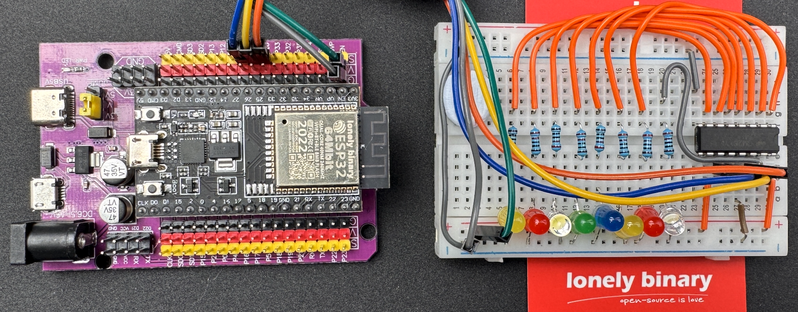
Diagram
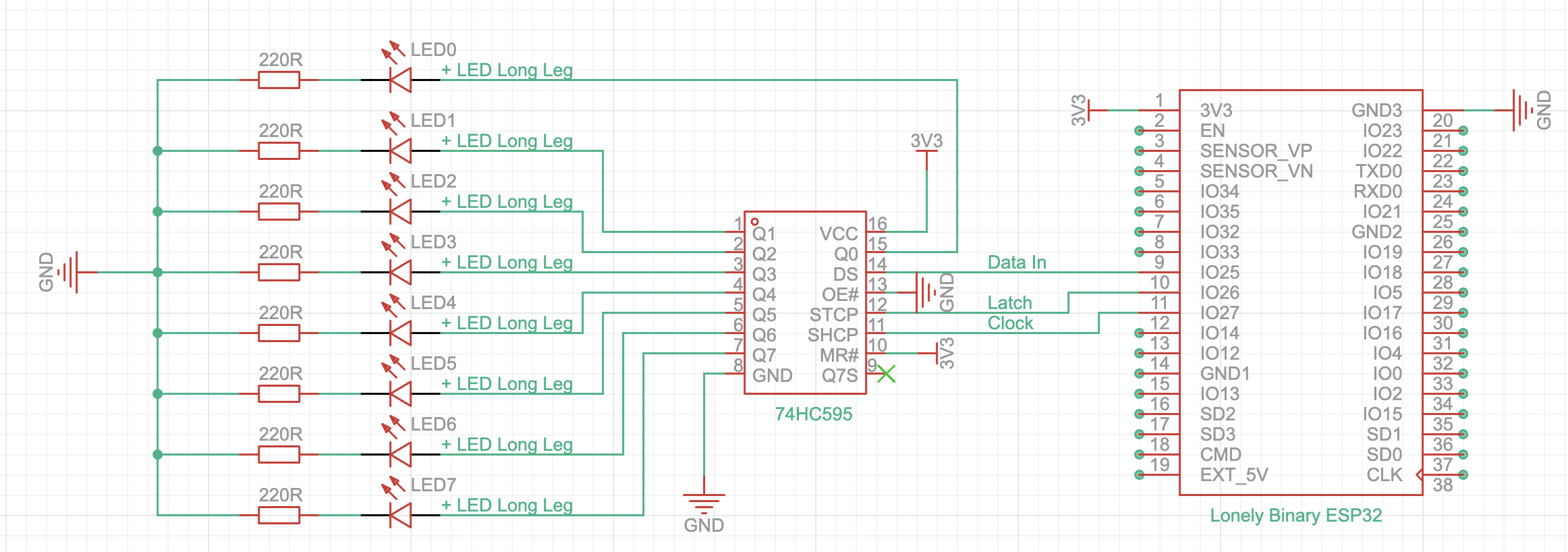
Schematics
| 74HC595 | Connection |
|---|---|
| Pin 8 | GND |
| Pin 10 | VCC |
| Pin 11 | Clock to ESP32 IO27 |
| Pin 12 | Latch to ESP32 IO26 |
| Pin 13 | GND |
| Pin 14 | Data to ESP32 IO25 |
| Pin 16 | VCC 3.3V |
| Pin 15 Pin 1 to 7 |
Connect the LED’s positive leg (long leg) to the output pin of the 74HC595. Connect the LED’s negative leg (short leg) to one end of a 220Ω resistor, and connect the other end of the resistor to GND. |
Basic Code
Let’s take a look at the simplest code to turn on an LED.
The 74HC595 requires three pins—Latch, Data, and Clock—to be connected to the MCU’s GPIO. These GPIO pins on the MCU must be set to output mode, as the data flows from the MCU to the 74HC595.
The latch pin is used to control when the data shifted into the shift register is sent to the output pins (Q0–Q7). Setting the latch pin LOW ensures that the data being shifted into the shift register does not immediately affect the output pins (Q0–Q7). This prevents intermediate or incomplete data from appearing on the outputs during the shift operation.
This line is using the shiftOut() function to send a byte of data (8 Bits) to a shift register 74HC595.
– dataPin: This is the pin connected from MCU to the DATA pin (Pin 14) of the 74HC595. It is where the binary data is sent from MCU, one bit at a time.
– clockPin: This is the pin connected to the **CLOCK ** pin (Pin 11) of the 74HC595**. Each time this pin is pulsed (LOW → HIGH → LOW), the shift register shifts in a bit from the dataPin.
- MSBFIRST: This tells the shiftOut function to send the Most Significant Bit (MSB) first.It means the data is shifted starting with the highest-value bit (leftmost bit in binary). In the case of 0b10101010:
- • MSB (Most Significant Bit) = The leftmost bit (1 in this case). When using MSBFIRST, the bits are sent in the following order: 1 → 1 → 0 → 0 → 0 → 0 → 0 → 0. The first 1 will be sent to Q7 of the 74HC595, and the second 1 will be sent to Q6. The LEDs connected to Q7 and Q6 will turn on.

-
LSB (Least Significant Bit) = The rightmost bit (0 in this case). When using LSBFIRST, the bits are sent in the following order: 0 → 0 → 0 → 0 → 0 → 0 → 1 → 1. Since the two 1s are sent last, they will be assigned to Q1 and Q0. The LEDs connected to Q1 and Q0 will turn on.

After all 8 bits have been shifted in, setting the latch pin HIGH transfers the internal data to the output pins (Q0–Q7). This ensures that the outputs are updated all at once, avoiding glitches or incomplete data appearing on the pins.
Try it Yourself
- Try changing from MSBFIRST to LSBFIRST and observe the result.
- Try converting the binary value 0b11000000 to its decimal equivalent (128).
Binary Display Code
A single 74HC595 shift register can control up to 8 LEDs. Each LED can be turned on or off, which is ideal for representing a binary digit. With 8 LEDs, you can represent a range of decimal numbers from 0 to 255.
Let’s create a simple binary counter that counts from 0 to 255 and displays the numbers using the LEDs connected to the shift register.

Limitation
Voltage Limits
74HC595 has a maximum supply voltage range of 2V to 6V, so it can’t handle voltages outside of this range. If the 74HC595 shift register is powered by 3.3V, the output voltage for each pin (Q0 to Q7) will also be 3.3V when the output is high.
Current Limits
The 74HC595 can source or sink a limited amount of current (typically around 6–8 mA per pin). It can only directly connect normal LED. You cannot connect high-current devices like Large LEDs, motors, or relays directly to the outputs.
If the external devices (LED, Motor, Relay) requires a large voltage (like 12V or 24V) and a large current, using an N-channel MOSFET is a great solution. The MOSFET will act as a switch, allowing the low-power signal from the 74HC595 to control the higher voltage and current needed for the LED.


