the VS1838B is a common and widely-used infrared (IR) receiver module. It’s designed to receive and decode infrared signals from remote controls, making it ideal for projects involving IR communication.
Key Features of the VS1838B:
- Operating Voltage: Typically 3.0V to 5.5V, making it compatible with many microcontrollers like Arduino, ESP32, and Raspberry Pi.
- Receiving Distance: Around 10–15 meters, depending on the strength of the IR transmitter.
- Frequency: Optimized for a carrier frequency of 38 kHz, which is standard for most remote controls.
- Wide Viewing Angle: Can receive IR signals from a range of angles.
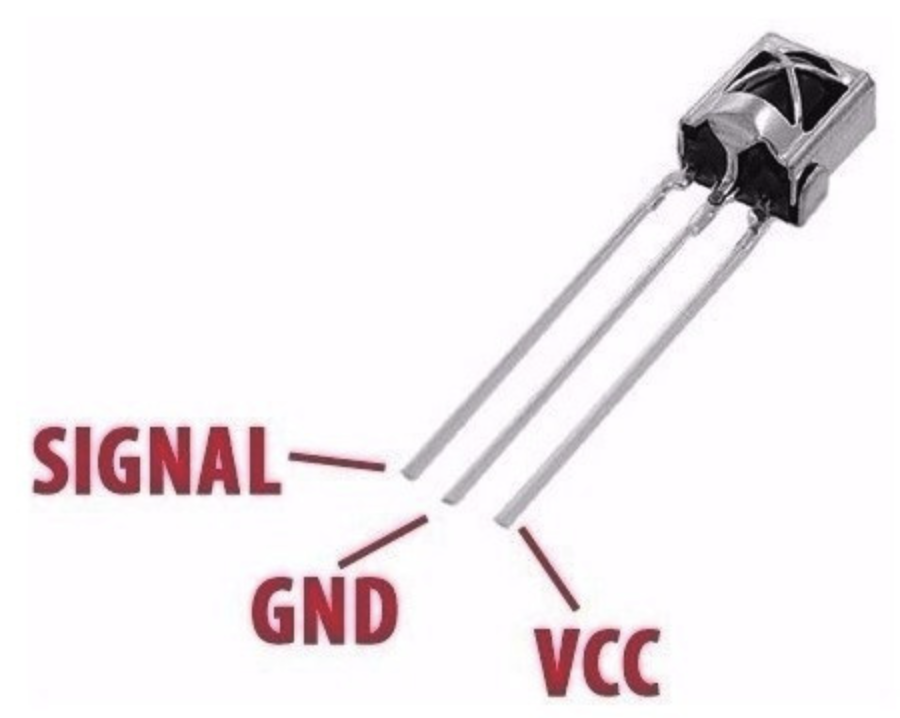
Pinout:
- OUT (Signal): Outputs the demodulated signal when it detects a valid IR signal.
- GND: Ground connection.
- VCC: Power supply (3.0V–5.5V).
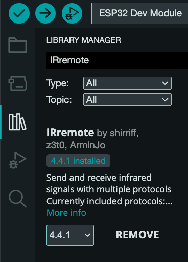
The Library we are using is IRremote by shirriff, z3t0, ArminJo.

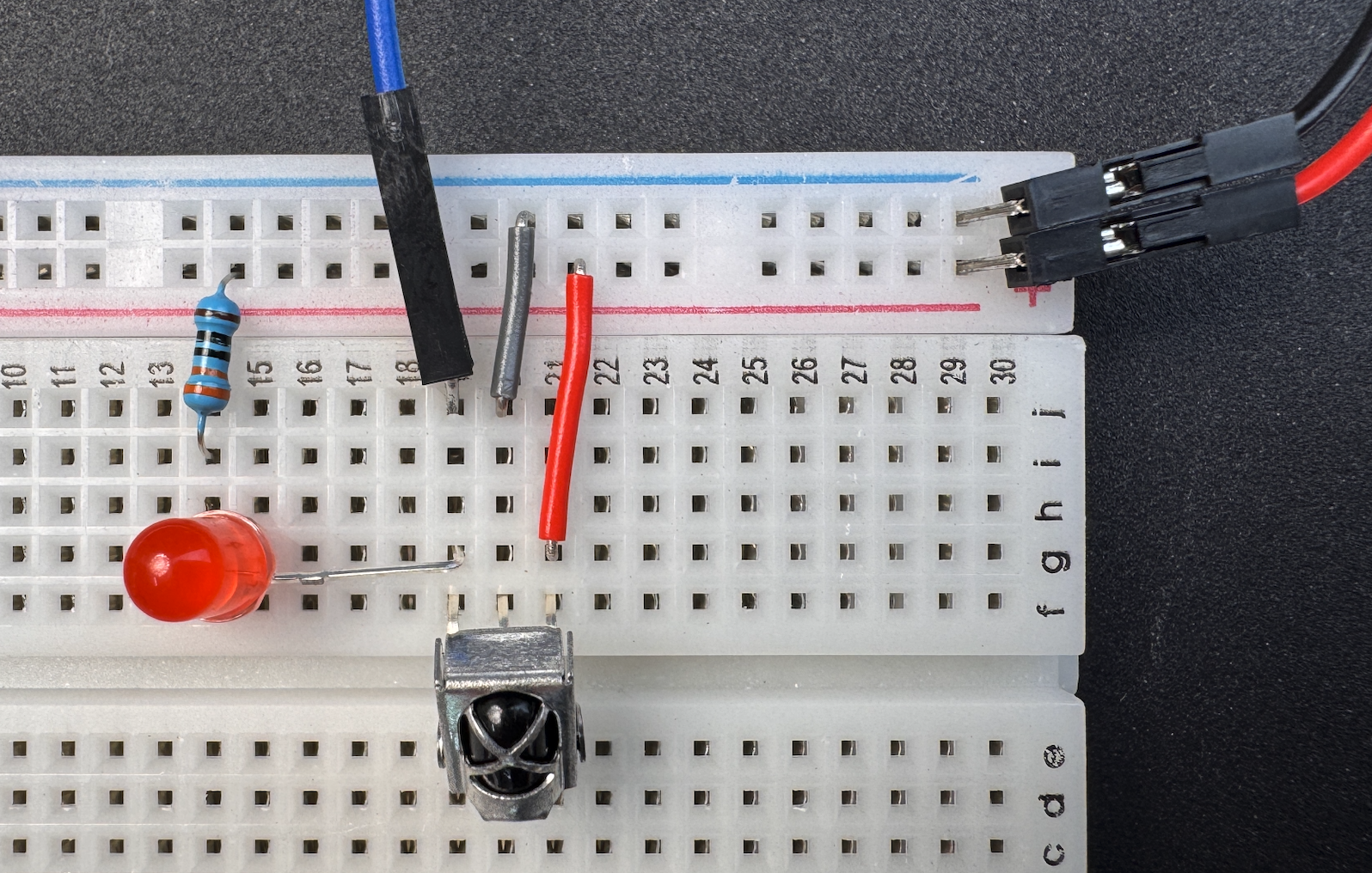
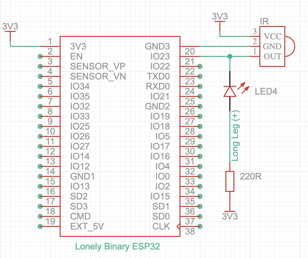
Connecting the VS1838B IR receiver to the ESP32 is straightforward. Simply wire the Signal Out to GPIO 23 on the ESP32, VCC to 3.3V, and GND to ground. You can also add an LED to indicate when the sensor detects a signal. Connect the short leg (negative) of the LED to the Signal Out pin of the VS1838B. The long leg (positive) of the LED should be connected to a 220Ω resistor, and the other end of the resistor goes to ground.
This code uses the Arduino-IRremote library to receive and process IR signals.
Configures the library to use a hardware timer for generating PWM signals (useful when sending IR signals, though this example is only about receiving).
This code is a bit unusual because it doesn’t have any assigned value. It defines a preprocessor flag, which can either be defined or undefined. The presence or absence of this definition controls which parts of your code are included or excluded during compilation.
Try running the below code. It creates a preprocessor macro named ENABLE_FEATURE without a value. The mere presence of this macro acts as a “switch” to enable or disable specific blocks of code.
Sets GPIO pin 23 as the input pin for receiving IR signals from the IR receiver module (e.g., VS1838B).
Initializes the IR receiver module to start receiving IR signals on the defined pin (23 in this case).
Checks if the IR receiver has received a complete and valid IR signal frame. Returns true if a signal was received; otherwise, it returns false.
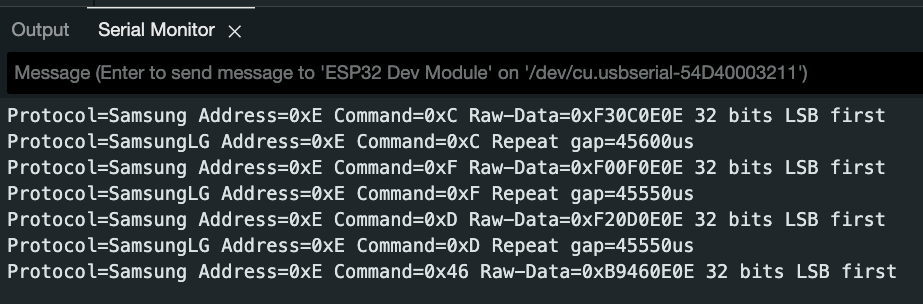
Prints a brief summary of the received IR signal to the Serial Monitor (e.g., protocol type, address, and command).
The &Serial is a reference to the Serial object, which represents the ESP32’s hardware serial communication interface. It tells the printIRResultShort() function where to send its output. On the ESP32, there are multiple hardware serial ports, and by passing the desired Serial object (e.g., Serial, Serial1, or Serial2), you can select which serial port to use for output.
This line checks the value of IrReceiver.decodedIRData.command, which represents the command received by the IR sensor from the remote. If the received command is 0x14, it prints “Volume UP” to the Serial Monitor, indicating that the user pressed the “Volume UP” button on the remote.
You can find the corresponding command address for each button on your remote control in the Serial Monitor.
Resets the receiver to be ready for the next IR signal.
Once a signal is received, the IR receiver stops processing further signals until resume() is called. Without calling resume(), the library will not detect or decode any new signals, effectively “freezing” IR reception.
The purpose of delay(10); in the loop() function is to introduce a short pause of 10 milliseconds between iterations of the loop. Without a delay, the loop() function would execute as fast as possible, continuously checking for new IR signals and processing them. Adding a small delay helps to regulate the execution frequency of the loop() and ensures the microcontroller isn’t running at full capacity unnecessarily.